Proficiency: Coordinating chaos
Identifying the fix on an approach procedure
Spokane WA USA")
(Photography by Mike Fizer)
 It seems too many candidates have trouble identifying the most important fix on the approach procedure. Instrument arrival and approach procedures are designed to guide aircraft from the en-route segment of a cross-country trip all the way to a decision point at which, with suitable weather conditions, the pilot takes over visually to land on the runway. If a safe landing cannot be assured, the pilot is compelled to apply climb power and execute the missed approach procedure in order to move on to Plan B.
That decision point, or missed approach point (MAP), is arguably the most important location on the approach because the aircraft can be within a couple hundred feet of the ground while its pilot has no visual references. What’s puzzling is how many candidates struggle to identify the MAP on an approach plate in the comfort of a briefing room. OK, maybe comfortable isn’t the right word for a practical exam—but if it’s not clear on the ground, it certainly won’t be in the air.
The MAP on any approach is a point in space that is identified using various navigational aids. The instrument landing system, or ILS, has served as the gold standard in leading pilots to a MAP that is often just 200 feet above the ground. A centered localizer needle means that the aircraft is on the two-dimensional vertical plane that contains the approach course. If the glideslope indicator is also centered, then aircraft is known to be somewhere on the line between the final approach fix (FAF) and the missed approach point.
Altitude narrows the aircraft position to a point in space. At the decision altitude (DA), the aircraft is at the MAP, so it makes sense to equate the DA with the MAP. The same reasoning applies to flying a GPS approach to LPV minimums. WAAS provides vertical guidance analogous to the glideslope indicator. Not all approach procedures involve vertical guidance, and without it, a pilot must plan her own descent profile to the MAP.
During the ground portion of the instrument rating practical exam, I often ask candidates to step through several different types of approaches, from an initial approach fix through the decision at the MAP. For an ILS or GPS/LPV, most correctly identify the MAP using the DA. For those without vertical guidance, candidates correctly report the minimum descent altitude (MDA) on the final approach course but have only narrowed the position somewhere along a horizontal line. Even though the MAP is typically presented in the profile view on the approach plate, some candidates can’t find it. My sense is that pilots are so accustomed to receiving vertical guidance (either approved vertical guidance from ILS or GPS LPV, or advisory vertical guidance as computed by the GPS navigator) that it’s easy to equate the MAP with an MDA but that is not correct in the case of an approach without vertical guidance.
If you’re prepping for an instrument rating practical exam or want a refresher, here is some advice on successfully planning a descent to the most important fix on the approach.
Understand the equipment required for the approach . The MAP can be a VOR, DME distance from a VOR or localizer, GPS waypoint, or time elapsed from the FAF, among others. For GPS approaches the MAP is often at the runway threshold and identified in the plan view as a flyover waypoint. For approaches you anticipate flying at your destination, IFR instructor Bruce Williams offers some great advice on using EFB marking tools to annotate important items on approach plates for easy reference in the air (bruceair.wordpress.com/2020/07/01/annotating-ifr-charts/).
Manage the descent profile . When I trained for my instrument rating, I learned the chop-and-drop method as a way to get down the MDA with the highest probability of seeing the runway environment at or before the MAP. But high descent rates in IMC can be disorienting, so it’s preferable to find a descent profile that provides a stable descent yet is efficient enough to reach MDA before the MAP. No equations are necessary here; given groundspeed and the descent gradient, the FAA’s Climb/Descent Chart provides the vertical speed that will get the job done. For this reason, I keep the chart as part of my electronic flight bag (see “There’s a Chart for That,” February 2019 AOPA Pilot ).
GPS navigators can do the math behind the scenes and adjust automatically for changing groundspeed. On a GPS/LNAV approach, you may see “LNAV+V” on the navigator—a sign that the unit is providing advisory vertical guidance. Just make sure not to confuse it with the approved vertical guidance of an ILS or GPS/LPV approach. Level out at MDA and don’t descend toward the runway until the required visual references are in view and you have sufficient visibility to avoid any obstacles on landing.
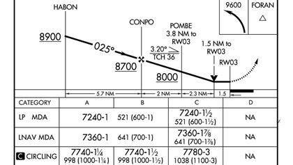
Incorporate the VDP . For many approaches without vertical guidance, an aircraft at MDA and at the MAP would have no way of continuing to land using normal maneuvers. A visual descent point (VDP), if shown on the profile before the MAP, offers an appropriate location to decide whether to continue the approach (if the runway environment is in sight) or to commence the missed approach procedure by climbing toward the missed approach hold.
Anticipate what you’ll see at the VDP/MAP. The airport sketch on the approach plate summarizes key information regarding what will be visible. An arrow representing the final approach course pointing toward the airport shows exactly how the runway complex will appear on the approach. Approach lighting information, taxiways, and displaced thresholds are also featured. Knowing what you should see when emerging from IMC can mean the difference between landing safely and needing to move on to Plan B.
The FAA’s Aeronautical Chart User’s Guide has a chapter devoted to U.S. terminal procedures and is well worth an afternoon’s read to bone up on the chart symbology. I earned my instrument rating in an aircraft equipped with just one VOR receiver with glideslope capability and marker beacons. When I first encountered GPS navigators in general aviation aircraft, I was impressed with how easy IFR flying had become. Alas, several years as an examiner and flying with such systems myself has dispelled me of that notion. GPS offers incredible situational awareness and brings reliable approach capability with low minimums to thousands of airports across the country. But the wide and continually changing array of technology provides a steeper learning curve for IFR candidates, as well as for instrument-rated pilots who want to maintain currency.
Catherine Cavagnaro
Related Articles