Mentor Matters: Takeoff V-speeds
The foundations of a safe departure

If an engine fails at any point, the pilot should be able to perform the appropriate procedure and effect a safe outcome. Regardless of altitude, temperature, or loading, a pilot who uses the approved performance data is sure to have an “out” at every phase of the departure. This ability comes from complex calculations and deliberate trade-offs performed by the manufacturer during the certification of the aircraft, and proper understanding of this process is a must for any jet pilot.
Important to this understanding is a deep mastery of the various V-speeds used in takeoff planning. While the pilot of a piston twin might only have a handful of fixed speeds in mind during a takeoff, such as VMC (minimum controllable airspeed), VR (rotation), and VYSE (“blue-line,” or single-engine best rate of climb), in a jet the pilot typically will be calculating as many as four to five different V-speeds that can vary significantly with each takeoff. Behind these calculated speeds lie several more critical speeds that constrain the range in which the takeoff speeds can exist.
An important fact to keep in mind as we study takeoff speeds is that most of the speeds are calculated, and not representative of an intrinsic aeronautical truth. Our first three speeds are selected by the manufacturer to maximize all-around performance, not because they reflect a state such as best rate of climb. These selections necessarily involve compromises and adherence to certification requirements that may limit the achieved performance in favor of increasing safety in another manner. These certification requirements, in turn, are driven by V-speeds that do reflect hard aerodynamic facts, so let’s start by examining these underpinnings.
VMC or minimum controllable airspeed is familiar to any multiengine pilot but takes on added meaning to the jet pilot. While a piston pilot typically deals with only one flavor of VMC, in jets two are used: VMCG (ground), and VMCA (air). Both affect how takeoff performance can be calculated.

Jet Takeoffs have four segments after brake release, V1, and VR: V1, and VR: from liftoff speed (VLOF) to gear retraction; from gear retraction to 400 feet agl; an acceleration phase; and the final segment, which is a climb to a departure procedure or enroute altitude. The final segment is flown at VFTO. Some manufacturers use the terns VAC (approach climb), VFS (final segment) or other V-speed terms instead of VFTO (top left).
The whole idea of balanced takeoff performance is to ensure that the distance to complete a takeoff to 35 feet agl and the distance to stop on the runway are the same. To realize that condition, test pilots experiment with higher and lower V1 values. Too low a V1 means you can easily stop on the remaining runway, but won’t accelerate fast enough to reach V2 within the length of the runway. Too high a V1, and you won’t have enough runway to stop if you decide to abort the takeoff. In this illustration, both airplanes begin the takeoff, experience an engine failure or other critical event at VEF, then either fly or reject the takeoff at V1. Both scenarios have safe outcomes, whether they continue the takeoff or carry out a rejected takeoff (RTO). The RTO means power to idle, aggressive braking—or using the RTO feature of an autobrake system—as well as deploying speed brakes or spoilers (center and bottom right).
Illustrations by Charles Floyd
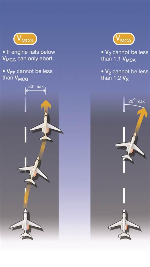
VMCG refers to the lowest speed at which a test pilot has demonstrated that directional control can be maintained on the runway after the critical (most adverse from a directional control standpoint) engine has failed. In flight, twinjets have no critical engine, but during the takeoff run the upwind engine is critical when crosswind conditions exist. Control must be regained with no more than 30 feet of lateral deviation from runway centerline, and must be demonstrated using only aerodynamic forces. No nosewheel steering is allowed. As VMCG is the lowest speed at which a pilot can be expected to safely stay on the runway with one engine failed and one producing takeoff thrust, if an engine fails below this speed the only safe option is to abort the takeoff. Bringing the operative engine to idle will remove the asymmetric force that is causing the airplane to veer off the runway.
VMCA is the lowest speed at which the test pilot has shown the aircraft can be flown with adequate directional control in an engine-out situation. Using no more than a 5-degree bank into the operative engine, the pilot must regain and maintain directional control after liftoff, with no more than 20 degrees of heading change from runway centerline allowed. As it would be unsafe to be airborne at a lower speed than this, VMCA controls how low our calculated rotation and climb speeds can be.
VS Stall speed has a greater effect on takeoff speeds in jets than in piston twins. As the stall speed of a jet is so much higher, the takeoff necessarily occurs with much tighter margins with respect to stall speed, and often is performed right to the edges of the certification limit. A light jet that loses an engine during the takeoff roll will commonly be climbing to 1,500 feet agl at only 20 percent above the actual stall speed for the current weight, whereas a piston twin may perform a single-engine climbout with closer to a 40-percent margin over stall.
VEF Our final speed that constrains and guides the calculated speeds is VEF, engine failure speed. This is the speed at which the engine is failed during the performance testing and validation of the aircraft before it is certified. The manufacturer is allowed to select VEF (at or above VMCG), but must use the same VEF to demonstrate both an aborted takeoff and a continued takeoff. Selection of an optimal VEF is essential for minimizing the runway required for takeoff.
Now, on to the calculated speeds.
V1 The first, and lowest, calculated speed for takeoff is V1. Unfortunately, what V1 represents is widely misunderstood by pilots. Often, pilots believe it is “takeoff decision speed,” or the highest speed at which an engine can fail and the pilot can properly abort the takeoff. This is subtly, but critically, incorrect.
Rather, V1 is defined in the federal aviation regulations as “the maximum speed in the takeoff at which the pilot must take the first action (e.g., apply brakes, reduce thrust, deploy speed brakes) to stop the airplane within the accelerate-stop distance.” If the pilot must take the first stopping action at V1, then clearly he or she would be reacting to an engine failure that occurred before V1 was reached. During certification this engine failure occurs at VEF, and the test pilot is required to wait one second before initiating the abort. The speed at which the brakes are applied is captured and published as V1.
 It is critical that pilots understand this clearly. An abort initiated even one knot above V1 will not result in the aircraft stopping in the published takeoff distance. By the time V1 is reached and noted, the only choice remaining is to continue the takeoff; the line separating stop from go has already been passed.
Pilots sometimes ask, “If the manufacturer can set VEF as low as VMCG, and the aircraft needs to be able to stop following an engine failure at VEF, why not publish a V1 as low as possible within these constraints? That way if an engine fails, the abort is being started at a very low speed, and the runway needed to stop will be minimal.”
The reason this is usually a suboptimal approach is that a second set of performance calculations must be done after those for the aborted takeoff is performed: the calculations for a continued takeoff after engine failure. The manufacturer must utilize the same VEF to calculate one-engine-inoperative takeoff distance, colloquially called “accelerate-go,” that it used to calculate the accelerate-stop distance with abort initiated at V1.
VR Here the next two calculated V-speeds come into play. The test pilot experiences an engine failure at VEF, but rather than aborting continues the takeoff until reaching VR—rotation speed. VR cannot be less than V1, and in many cases it is set to be exactly the same as V1. VR also must be at least 1.05 times VMCA to ensure that directional control is possible, and it must be shown to allow safe liftoff from the surface. The pilot rotates the aircraft at VR, the aircraft lifts off when at the appropriate pitch attitude, and reaches the third calculated takeoff speed no later than when reaching 35 feet above the runway—V2.
V2 is even more misunderstood than V1; even experienced pilots often believe an incorrect definition that equates V2 to VXSE, or best angle of climb with one engine inoperative.
Instead, the FAA defines V2 as “takeoff safety speed,” and that’s all it is—a safe speed at which the aircraft can climb on one engine, and will achieve by 35 feet agl following an engine failure at VEF. For light jets, V2 must meet three criteria: It must provide a small margin (20 percent) over stall speed, a smaller margin over VMCA (10 percent), and must allow for a minimum engine-out climb gradient of 2 percent, meaning that for every 100 feet forward the aircraft travels, it must climb at least 2 feet.
For all but the most extreme cases of high weight and density altitude, light jets have enough thrust on one engine to make the required 2-percent gradient even when flying at a non-aerodynamically optimal speed below VXSE. Since the point at which the aircraft reaches both 35 feet and V2 is where the accelerate-go distance ends, and since this distance must be equal to or less than the amount of runway present (excepting the extremely rare case where a designated clearway exists at the end of the runway to allow for climb to 35 feet after the runway has ended), it is in the manufacturer’s interest to calculate as low a V2 as is allowed, to minimize runway required for takeoff.
If we reverse-engineer the continued takeoff we can see why a very low V1 isn’t always the best overall answer to the speed calculations. With the minimum allowable V2 as our target, VR cannot be set too low or this V2 won’t be achieved by 35 feet. This minimum VR, in turn, must be achieved after the engine has failed at VEF. The implication is that for the period between VEF and VR, the aircraft is being accelerated by only one engine, so will need roughly twice the distance to get to from VEF to VR.
The manufacturer is now faced with the need to balance two competing interests. A low VEF/ V1 will reduce accelerate-stop distance but increase accelerate-go, while a high VEF/ V1 will do the opposite. The pilot must have enough runway to meet both accelerate-stop and accelerate-go requirements, so having these two numbers unequal is said to be unbalanced, and does not allowed for the shortest possible runway requirement. A balanced V1 is one calculated so that if the engine fails at VEF, the test pilot can demonstrate that accelerate-stop and accelerate-go are exactly the same, and the runway required for takeoff will have been minimized.
Runway analysis and VFTO
So now let’s say our aircraft is 35 feet in the air with a (small) margin over both VS and VMCA. The aircraft is achieving at least a 2-percent gradient—corresponding to a roughly 200-fpm climb. Our next problem is ensuring that until the aircraft reaches an altitude that allows for a return to our departure airport, or diversion to a takeoff alternate, we are able to climb at an angle and on a path that allows for terrain clearance. Remember that we are in a somewhat undesirable aerodynamic state—often with flaps deployed, thus experiencing their associated drag, and on the back side of the power curve below the optimal speed for best angle of climb.
Fortunately, manufacturers provide detailed performance information that can be combined with terrain and obstacle databases to compare needed versus expected engine-out performance for any airport at any weight and atmospheric conditions. This task is too complex for all but the largest operators to do themselves, so third-party “runway analysis” services are called upon. Their software will quickly tell the pilot if the airplane will outclimb terrain at the planned takeoff weight, and if not, how much weight reduction is required.
The runway analysis also will calculate for the pilot the important acceleration altitude: the altitude at which the airplane can momentarily level off and accelerate to our last calculated speed—VFTO, or final takeoff speed. Manufacturers often relabel VFTO according to their own convention, calling it VFS, for final segment, or VENR, for en route climb speed, in the case of two large manufacturers. It is calculated to allow for the optimal angle of climb after flaps have been retracted, and the thrust of the operating engine has been reduced from the takeoff setting (which is time limited) to the maximum continuous setting.
As the aircraft accelerates from V2 to VFTO the flaps are retracted according to a schedule that allows for continued operation safely above stall speed. Typically, this schedule requires that a speed 10 to 15 knots above V2 be reached before the flaps can be retracted, or as much as 20 to 25 knots if the takeoff was performed using the maximum flaps setting allowed.
Putting all our speeds together, we see how the full departure regime allows for a safe out:
Abort at or before V1 and the aircraft will stop in the published takeoff distance.
Continue on one engine at or above V1 and the aircraft will fly safely above VS and VMCA, and will clear terrain if the maximum weight calculated by runway analysis software is respected.
The precise point at which the aircraft can be cleaned up, and the speed at which to continue the en route climb, will already have been calculated—ensuring the pilot need only “fly the plan” to bring the aircraft safely to an en route altitude.
Neil Singer
Related Articles