April 2012
Turbine Pilot Contents
- L-39: Cool Flying. 'Nuff Said. Special section for the turbine inclined.
- Flying a 'Real' Jet Making like Maverick in an L-39.
- For Pax Sake Practical tips to make the flight more comfortable for your passengers.
- Mentoring Matters: FARs for Jets Regulations that apply to operating jets.
- Trouble for Throttle Jockeys Easy does it when settling takeoff power.
- Turbine Market Shows Mixed Signals Light turbine market continues to struggle.
- Glass Cockpits: Moving Targets Now invading GA.
Despite the fact that everyone talks about glass-cockpit airplanes today as if they are as common as power windows on a new car, glass-panel displays are actually relatively new to general aviation, on the scene within the past decade or so. But glass has been standard equipment for decades on transport-category airplanes such as the Boeing 757/767 series, MD–80s, and some early Airbus models.
When the 757 made its first flight in 1982, flight crews were amazed—some would say overwhelmed—by both the volume and the then-unique fashion in which information was presented. Gone were many of the mechanical gauges everyone had once depended upon for attitude, speed, altitude, and navigation cues. All were replaced with computer-generated representations of systems that more tightly integrated data onto a single screen, now labeled a primary flight display (PFD), and a multifunction display (MFD) to graphically present navigation data. In later aircraft, engine instrumentation also appeared on the MFD as the navigation morphed into the flight management system (FMS).
Looking at glass cockpits as simply computer-generated versions of steam gauges, however, seriously sells these marvelous tools short. For starters, glass generated a revolutionary new standard to the old “T” instrument layout. Airspeed, for instance, was now displayed as a moving vertical tape to the left of the attitude indicator; altitude on a tape to the right; and vertical speed to the right of altitude information. Final approach guidance is now displayed just beneath the attitude indicator, demanding that pilots somewhat alter the decades-old system of scanning the panel. A bonus feature is the color and animation options computers offered over traditional black-and-white mechanical displays.
Being human, of course, not all pilots enjoyed these changes. Some thought too many colored, moving icons were simply overwhelming, despite the claims of improved safety. Quite a few gray-haired airline pilots stumbled during the transition to glass, and a few never successfully completed the transition.
Glass was labeled early on as certain to improve safety, and a 2011 NTSB report took a close look at how glass altered the general aviation landscape. “There is little in the way of added safety benefit [to glass cockpits]—yet,” the report said. The good news, of course, is that in sheer numbers, glass-cockpit aircraft were involved in fewer total accidents than some had predicted. The downside, however, was that more of the accidents that did occur resulted in fatalities. Flight training is still, for the most part, trying to catch up with the glass-panel technology.
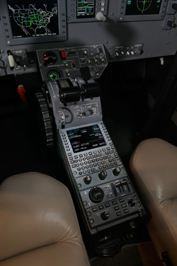 Collins FMS 3000 in the cockpit of a Citation CJ3.
Try it, you’ll like it
With the Rockwell Collins Pro Line 21 system as a guide, here’s what a typical business aviation pilot needs to understand about the display before hopping into the left seat of a Cessna Citation CJ3. Although the depth of features is somewhat less on smaller training airplanes, today’s Avidyne- and Garmin-equipped Cessnas, Diamonds, Pipers, Hawker Beechcraft, and Cirrus offer options that rival those found on the CJ3.
The focal point of any glass airplane is the PFD that mimics elements of the basic “T” configuration every pilot has come to rely on. The beauty of glass is a number of useful new tools—such as trend information—accessible for almost no additional scanning effort. With so much data packed into one location, the pilot’s overall scan is, in fact, considerably easier than in a traditional steam-gauge aircraft. How much a pilot’s brain can interpret is, of course, another matter.
Standard layout includes the airspeed tape, attitude indicator, altitude, and vertical speed indicator. The bonus is a horizontal situation indicator (HSI) replacing the heading and course indicator offering distinct visual guidance and even weather information in one location. In the example (above left), the aircraft we’re flying is represented by the set of white wings and stabilizers in the center of the HSI.
Additional PFD data include the assigned altitude that the alerting system compares with actual altitude. The PFD also displays the transponder code, communications frequencies, and the next flight plan waypoint programmed in prior to takeoff. In the example (above left) the CJ3 is flying at 250 knots indicated airspeed, level at FL 370 on a heading of 046. The FMS indicates the next point in the flight plan is COOLI intersection, 12 miles ahead. ATC code is 4250 and the pilot’s number one radio is tuned to 121.6.
Beginning just 20 miles ahead and to the left of our planned course we can see some approaching rain that grows into a pretty significant chunk of weather in 45 miles. This gives the pilot the time to alter course to avoid it. At this distance, a right turn of about 10 degrees should keep us clear of most of the heavy cells.
The MFD, normally set in the center of the instrument panel, is aptly named because of the variety of information the screen is capable of displaying. One of the inherent beauties of glass panels is their ability to quickly morph into just about anything the pilot needs. Should the PFD fail en route, the MFD can be set up to act and display precisely the same information.
On page T–22 (right), the MFD is set to display navigation information on a trip between Salt Lake City (SLC) and Columbus, Ohio (CMH). Our aircraft is visible in the center of the display.
At the bottom of the screen, the system indicates a groundspeed of 464 knots, with a true airspeed (TAS) of 430 knots. Farther right are two temperature indications. SAT relates to the static air temperature, while ISA is our relationship to international standard atmosphere, a number critical to determining climb and cruise performance up high. In more sophisticated jets, the MFD can also function as the engine-management center with all pressure and temperature gauges, not to mention a variety of diagnostics and warning functions.
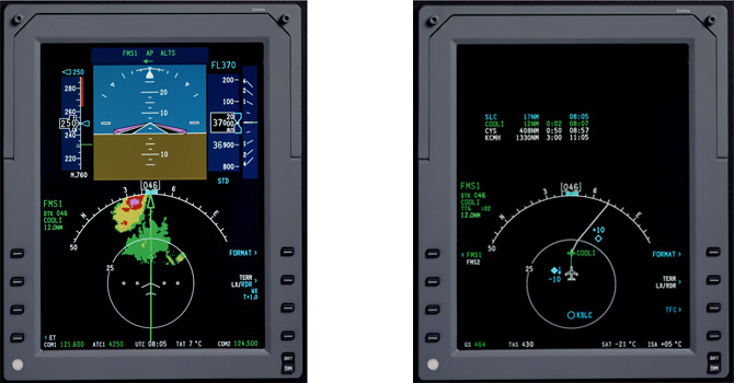
Using a PFD, everything important to aircraft control, including weather, is located on this easy-to-read instrument (left). On the MFD, pilots can quickly answer when they will reach their destination (right).
To the left of the airplane icon is a traffic collision avoidance system (TCAS) indication of another aircraft passing safely by 1,000 feet beneath us (the minus sign). The down arrow indicates that same aircraft is also descending. Just after we pass the COOLI intersection ahead, we’ll be on the lookout for more traffic level 1,000 feet above (the plus sign). We also should note that under autopilot guidance, the aircraft will turn right just after passing COOLI in order to remain on course. The data near the top of the screen is nice-to-know flight plan information, such as distance to destination, 1,330 nm, and that we should arrive in Columbus three hours from now.
Getting there from here
Although the pilot interface keyboard in the Pro Line 21 system—called a control display unit (CDU)—might look complex, it’s nothing more than a sophisticated version of some of the same GPS systems used in most GA airplanes today, minus the knobs. This CDU interface between the pilot and the onboard database-driven flight management system (FMS) allows for rapid entry and retrieval of information with minimal head-down time on the part of the pilot. It normally sits just beneath the MFD and aft of the thrust levers for ease of data entry. The FMS receives and processes the flight planning information necessary to begin and safely complete a flight using GPS, VOR, and other navigation signals.
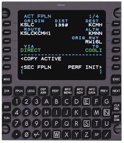 Most pilots are spoiled after the first flight using a data-entry keyboard over the more cumbersome knob twisting.
Using the keyboard, the pilot can input the entire flight plan by typing the information in one element at a time. The vertical black buttons along the sides allow the pilot to pick out any particular point along the route should the flight plan need updating. For instance, if ATC re-clears the flight direct to a point a few hundred miles down the road, the pilot merely chooses that point from the flight plan and hits the Direct-To (DIR) key. On autopilot, the aircraft then heads for the new point.
The FMS also contains every IFR approach procedure for every airport in the FMS database. So when ATC says, “Expect the ILS Runway 28 Left at CMH,” the pilot makes a few quick entries that arm the system in preparation to switch to and follow guidance to that runway. The CDU is also the location where the pilot changes all radio frequencies and transponder codes, as well as gross weight and runway-required data. This display also functions as a fuel management page and provides access to the aircraft’s vertical navigation functions (VNAV).
Glass cockpits also provide an element of maintenance simplicity. If a PFD fails, three or four screws later and the old display can be replaced with a new one. Traditional airspeed, static, and altimetry sensors are attached outside of the glass units, making them easier to replace too.
One significant problem glass cockpits have added to flight is the distraction factor common to anything moving in a pilot’s field of vision, not to mention some overreliance on the accuracy of all on-board computers. But the onslaught of glass aircraft into GA is unstoppable. While glass offers an abundance of useful features in today’s fully integrated cockpit, learning how to use these new tools effectively, while still maintaining control of the aircraft, is something sure to keep flight training organizations busy for years to come.
Robert Mark is the editor of JetWhine.com, an award-winning aviation blog.